Light-Up Neuron
- Published27 Sep 2017
- Reviewed27 Sep 2017
- Author Emma Lindberg
- Source BrainFacts/SfN
The brain is made up of around 86 billion neurons, which are nerve cells specialized for the transmission of information. When neurons receive or send messages, they transmit electrical impulses along their axons. These electrical signals start at the cell body and end at the dendrites.
Similar to a neuron, a circuit is the path that an electric current travels on. With a few simple materials, students will build their own circuit with a blinking slide switch to better understand how messages travel down a neuron.
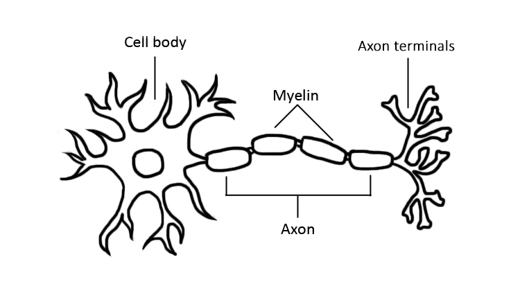
Teacher Background
Chibitronics has created dozens of templates that students can use to build out simple or elaborate circuits. Following their blinking slide switch model, your students can build a functioning, blinking neuron with the template provided below.
Materials
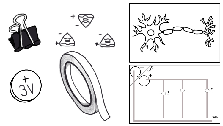
Provide each student or group with the following materials:
- One circuit template and neuron sheet Download (PDF, 76 KB)
- One coin cell battery (which Chibitronics recommends storing away from other metals)
- One binder clip
- At least 30 inches of copper foil tape
- Three LED stickers
Optional
- A two inch piece of tape
- A paperclip
Step 1
Print out the circuit and neuron templates, then distribute all the materials to your students. Students may do this activity individually or as a group. For the purpose of these instructions we will be referring to students as individuals.
Step 2
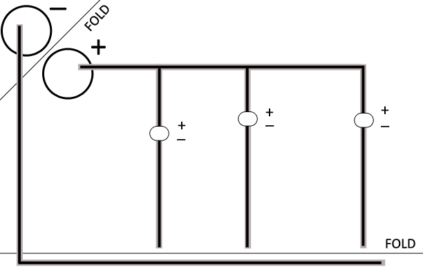
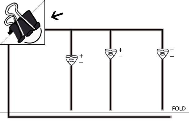
Ask your students to place their copper foil tape on the circuit template. The foil is represented as black lines in the above example. They should only place the foil on the grey lines, making sure to leave space in between the positive and negative side of the ovals. This space should be small enough that the gap can be covered by the LED stickers, but wide enough that the foil is not touching.
According to Chibitronics, students should “apply the copper tape as a continuous piece, rather than separate pieces, even when turning corners” as much as possible. When students cannot use the tape in a continuous piece, it is ok to cut the foil and have the copper foil overlap with other pieces. The adhesive on the bottom of the foil tape will lead to a weaker connection if students overlap, so some lights may not be as bright as others.
Step 3
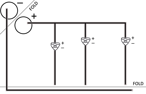
After students have covered all the grey lines with copper foil, ask them to place the LED stickers on the ovals.
Remind them to make sure the positive side (the larger side of the triangle) is at the top of the oval. Students should make sure that both the positive and negative sides of the LED stickers overlap with the foil. Also, all the LED stickers should be facing the same direction.
Step 4
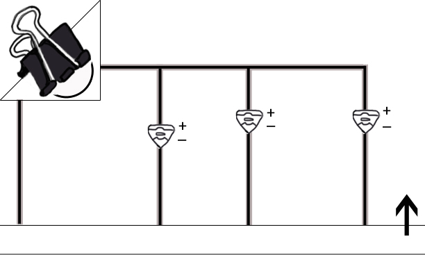
Ask your students to crease along the FOLD line in the upper left corner. The small fold will house the battery, which according to Chibitronics provides power to your circuit. Ask them to reopen the FOLD, and place the battery with the positive side down on the paper. Then prompt your students to fold the top of the corner over onto the negative side.
Students should make sure the copper foil tape is touching the battery on the positive and negative side. Once this is confirmed, they will use the binder clip to hold the battery in place.
Step 5
Once the battery is secure, tell your students to fold along the long FOLD line at the bottom. Students should make sure that the copper tape below the long FOLD line touches the three lines of copper tape above the FOLD line.
Step 6
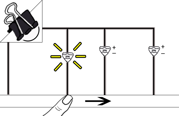
Students will run their fingers across the slide switch from left to right to make sure the lights are properly working.
If students are having problems getting their switches to work they can try one of the following:
- Make sure the positive side of the battery is face down.
- Make sure the copper foil tape touches both sides of the battery.
- Make sure there are no breaks in the copper tape.
- Make sure the LED stickers are facing the correct direction. If students have put their stickers on upside down, they can flip their battery over so the negative side faces down.
- Make sure the LED stickers overlap on the copper foil tape on both the negative and positive ends.
- Make sure all the LED stickers are facing the same direction.
- Make sure the copper foil tape overlaps in places where it could not be folded or bent.
- Make sure the copper foil tape along the bottom of the FOLD line touches the three lines of copper foil tape above the FOLD line.
Step 7
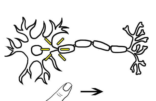
Once the slide switch is operational, students can place their neuron print outs on top of the circuits. They should make sure the cell body is on the left side of their paper. Students should also make sure the two upper right corners of their circuit and neuron template line up. One option is to use some tape or a paper clip to hold the two pieces of paper together. Tell your students to run their fingers from left to right along their slide switch through the neuron paper.
Step 8
Take a moment to point out the direction the signal travels and the three places where the lights appear on the neuron.
Electrical signals in a neuron travel from the cell body, down the axon, and to the dendrites. They do not travel the opposite direction.
Electrical signals do not go into the cell body or the myelin, and once they reach the dendrites they do not cross to another neuron. Instead, neurons release chemicals called neurotransmitters into the space between neurons, which activate receptors in the next neuron to start the electrical signal there.
You can learn more about how neurons communicate on BrainFacts.org
CONTENT PROVIDED BY
BrainFacts/SfN
Also In For the Classroom
Trending
Popular articles on BrainFacts.org


